Spherical Disc Springs / DIN 2093 Group C · spherical +1 (S/R) convex
10.00*5.20*0.25*0.55
Dimensions, standards and downloadable engineering files are generated from published product data.
- Outside diameter De
- 10.00 mm
- Inside diameter Di
- 5.20 mm
- Product thickness t
- 0.25 mm
- Free height l₀
- 0.55 mm
- Cone height h₀
- 0.30 mm
- Standard
- DIN 2093 dimensions / spherical +1 (S)
- Material / surface treatment
- 50CrVA (BLACK_OXIDE)
- Temperature
- -50 – 300 °C
ENGINEERING FILES
CAD / DXF / STEP
Repository CAD · member download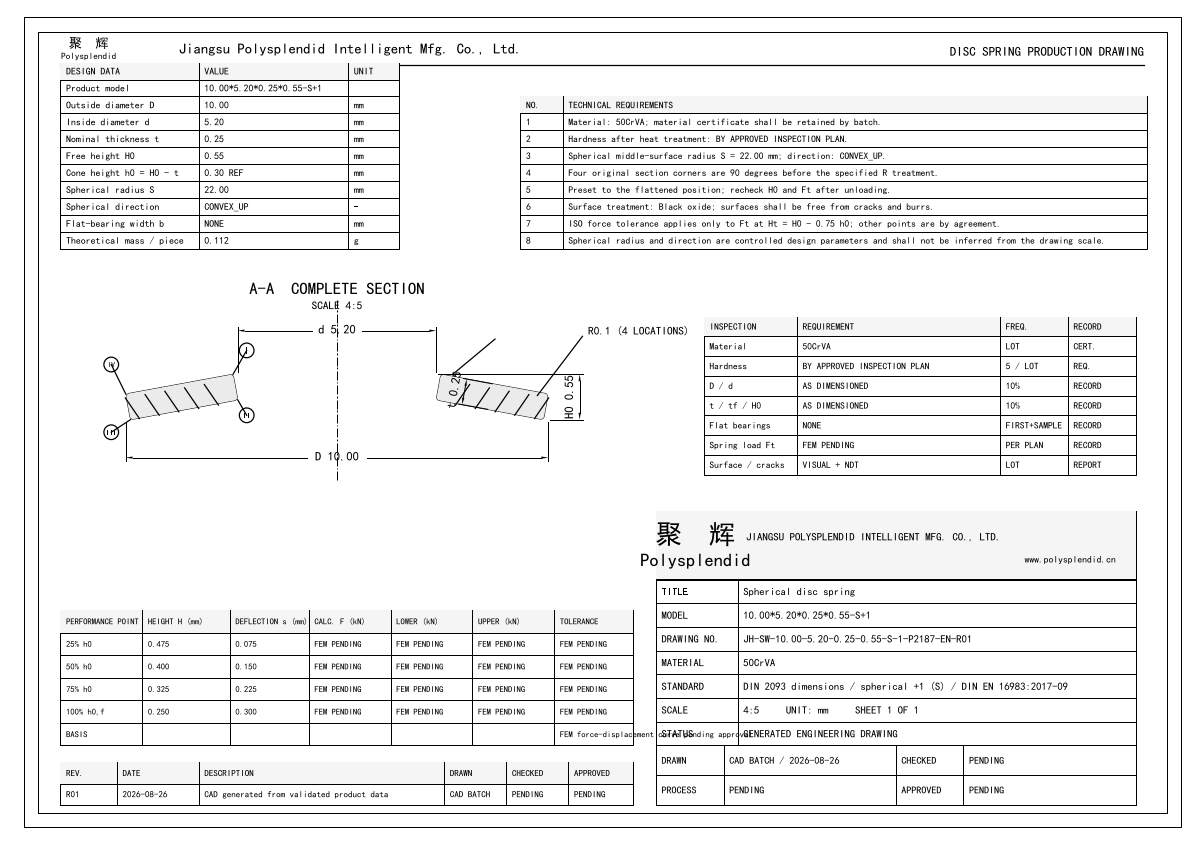 Open full drawing preview
DWG10.00*5.20*0.25*0.55-S+1 DWG CADJH-SW-10.00-5.20-0.25-0.55-S-1-P2187-EN-R01.dwg · 50 KB
Member downloadDXF10.00*5.20*0.25*0.55-S+1 DXF CADJH-SW-10.00-5.20-0.25-0.55-S-1-P2187-EN-R01.dxf · 127 KB
Member downloadSTEP10.00*5.20*0.25*0.55-S+1 STEP CADJH-SW-10.00-5.20-0.25-0.55-S-1-P2187-R01.step · 22 KB
Member downloadSTL10.00*5.20*0.25*0.55-S+1 STL CADJH-SW-10.00-5.20-0.25-0.55-S-1-P2187-R01.stl · 1.6 MB
Member downloadSPECIAL SURFACE GEOMETRY
Special-surface definition
spherical-midline-v1 · AThe meridian is defined by the mid-surface spherical radius S (R) and its orientation.
- Surface family
- Spherical Disc Springs
- Design code
- SPH-S+1-P373
- D
- 10.00 mm
- d
- 5.20 mm
- t
- 0.25 mm
- H₀
- 0.55 mm
- RI
- 0 mm
- RII
- 0 mm
- RIII
- 0 mm
- RIV
- 0 mm
- Mid-surface spherical radius S (R)
- 22 mm
- Camber ratio gamma_W (design rule)
- 0.11
- Spherical orientation
- Convex
- CAD geometry status
- defined
- FEM validation status
- not_started
Only geometry revisions linked to a formal product, technically approved and published are shown. FEM status alone is not a performance claim.
ENGINEERING OVERVIEW
Candidate decision overview
Data version 3GEOMETRY CONTRACTSpherical profile
- Bearing surfaces
- No
- Tolerance grade
- See dossier / confirm
Special surface parameters must be reviewed against the released drawing; the profile name alone is not a complete geometry definition.
EVIDENCE COVERAGE—Manufacturer curve / stressNot public—Polysplendid calculationsNot public—Resolved standardsNot public—Inspection dossierNot public—Approved product FEMNot public
A missing FEM record is not evidence of failed validation. It means no approved product-level study is public on this page.
COMBINATION BOUNDARYCheck single disc before stack
Parallel stacks primarily multiply load; series stacks primarily multiply travel. Friction, contact, guidance, preload and manufacturing scatter must be checked separately.